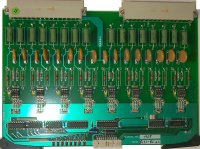
Digital Isolation Module
5421 or SENS 421
VERSIONS
| -01 | 220V DC |
| -02 | 110V DC |
| -03 | 60V DC |
| -04 | 48V DC |
| -05 | 24V DC |
CONNECTS TO
Digital Input Support or High Density Support
Acquisition Controller
FUNCTION
This Printed Crcuit Board (PCB) is an eight input device. Its function is to SWC protect its inputs, scale its inputs using user factory set resistors, optically isolate and condition the inputs, and place the signals on the ribbon cable, according to its card address jumper settings.
Sixteen LED's provide status at a glance. Eight yellow LEDs are in circuit with the inputs, and will illuminate when a voltage is present in the circuit (usually indicating a closed field contact). Eight red LEDs, located along the front edge of the PCB, illuminate to indicate the programmed status of the inputs, either NORMAL or ALARM. Each input is programmable through the software as Normally Open or Closed.
JUMPER SETTINGS
A single jumper, labeled J1, is on this PCB. It is located near the ribbon cable connector. It is a 3 position device, and must be set according to the channels addressed by the board:
| PCB #1 | PCB #2 | PCB #3 | |
| Channels | 1 - 8 | 9 - 16 | 17 - 24 |
| Address | J1 - 1 | J1 - 2 | J1 - 3 |
BOARD LAYOUT
PICTURES
NOTES
