
ARES/RACES |
Antennas |
Public Service Events |

![]()
Automatic Position Reporting System
This technology (not new either) allows us to locate the position of assets that have the equipment, wether they be in a vehicle, or carried by a walker, cyclist, etc. It also allows basic message communications and the ability to connect 3rd party weather stations and broadcast this information.
To evaluate this technology and its ability to support the many Public Service Events the club supports, I have compared a few software packages, and hardware platforms. Some of these will be discussed here.
Along the way I will place relevant web links to aid you in your own evaluation. No discussion of APRS would be complete unless I pointed out the father of this system, Bob Bruninga, WB4APR and his comprehensive website.
In its basic form, APRS has two parts, a station and a tracker. There are variations, so please don't flame me for making this generalization.
TRACKER
A tracker consists of a transmitter and a TNC (programmed). A tracker does not need to have teh full capabilities of a TNC, and many are available that transmit only (report their positions).
STATION
A station could simply be a computer running any of the popular APRS programs, and an internet connection. More typical would be a station setup for RF, which would consist of aTNC, tranciever and computer.
Being a hardware kind of guy, I started here.
To begin playing with this technology, I dug out an old mobile tranceiver I had used with packet radio, years ago, and its TNC. The tranceiver is an Icom IC-255A and the TNC is an AEA PK-88 (more on that later).
After much experimentation with the hardware & a couple of software packages, I was informed that the character that the PK-88 uses between digipeters is not in the APRS standard & the program I preferred did not support that character! So I was fortunate to get a PacComm Tiny-2 MK-2 TNC from a friend, and built a cable harness for it. I was unable to get this TNC to work as expected, and panicked. I needed to feel comfortable with the hardware before I could confidently evaluate the different software available, so I ordered what is considered by many as the 'standard' APRS TNC, the Kantronics KPC-3+.
In the mean time I mentioned to my friend that I was unable to get to Tiny-2 work, and he swapped with me, one that he was using & he knew worked. Well, this one took off with only a baud rate change, and I was getting reports of APRS trackers off RF.
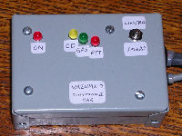
| The club has 2 APRS tracker systems, currently programmed with WA2UMX-8 and WA2UMX-8. This is a photo of the hardware. |
Last year (2005) I helped out at net control for the ADA Tour de Cure in our area. I was exposed to APRS in use at its early usage in this event, and worked with Dick Jenkins (pioneer in this area for our club), and was intrigued.
This year I volunteered to get more involved. First I wanted to evaluate the different programs that are available to display APRS information. I found the following:
WinAPRS
APRSPoint
UIView32
AGWPE
I located the latest version of these programs, and downloaded them to my laptop. I was fortunate to have a coconspirator in Jim, K2LM, who was able to drive around with one of the club's trackers in his vehicle for testing.
I heard much praise for WinAPRS, so I looked into it first. The evaluation version has all the functionality of the licensed version, but discards all the settings you make, each time you close the program. This program relies on Tiger Maps for detailed mapping.
I was able to input all the needed settings for this program, and talk to my PK-88, and begin receiving APRS plots and messages immediately. This program also has an 'AEA' mode, as well as a KISS mode for TNC communications.
After a while, the base maps became annoying, so Jim was kind enough to let me install his Tiger Maps on my PC. I believe these were compiled by Frank KA2QYE. Installing them was simply copying them to the needed folder. The next time I ran WinAPRS, it loaded all the county maps with great detail.
I then evaluated APRSPoint. I already owned a copy of the Microsoft MapPoint mapping program that is the base for APRSPoint, and was pleased to see that I could buy only what I needed. This is the program that was used by Dick at the Tour in 2005.
I got this program installed and began to use it to get familiar with its features. Fortunately I was familiar with the Microsoft product, so the learning curve was not that steep. After some time I discovered that I was not seeing Jim all the time, but when he returned to his home, he had tracked his travels with no troubles from his APRS Station. So I began a conversation with the author of APRSPoint, regarding my problem. After more testing and sending raw TNC data to him, he informed me that his program would not decode the digipeated packets if they were seperated with a greater than (>) symbol (which the PK-88 uses), because that was not the correct character. In the APRS specification, the comma (,)l was the correct character, and only those packets that I heard directly were being decoded. Well, OK, I thought, that is too bad. I then examined the referenced APRS spec, and found a section of the spec that specifically referred to the AEA and its foibles. Apparently he did not want to implement that functionality I thought... Too bad.
Other than that, I was much more pleased with this programs ability to mark points on maps, trace routes, and locate points by entering coordinates, so purchased a license for it. This also allowed me to access the internet APRS servers, so I did not even need to be connected to a radio & TNC to see the action. It did force me to learn more about internet APRS servers, their recommended useage, and teh FILTER settings in the program. Setting a filter on TCP to limit the radius of reported stations to 60 miles allowed me to regionalize the amont of data on the map. Otherwise, every report for the entire world tried to display (I know, I tried it first...).
I then got hold of a PacComm Tiny-2 MK-2 TNC which is much newer than my PK-88 and had native support for GPS as well. Once I built a cable for this, I tried it out (see hardware above for trials). I then got a replacement, and was off and running.
I plan to use this APRS porgram for the Tour de Cure this year.
I have made a tracker using an old Heath (Standard) H/T, a Byonics TinyTrack 3 (TT3), an old Garmin GPS unit, and an external battery. This works great as a portable system. Recently I purchased a Conterra radio harness to hold all the gear on a person, making it person-portable.
I have been busy making the trackers more consolidated and transportable for the upcoming events, and adding to the number of systems we have. It seems that once the served agencies see what is possible, they clamor for more!!
UMX-7 and -8
 |
Byonics Tiny Track2 (TT2), Yaesu FT-1500M, Delorme Earthmate GPS, GST-1 adapter. These systems were custom assembled by Dick (W2GWY-SK), and the TT2 were installed inside small metal bud boxes, including a switch to select between the 2 profiles possible in the TT2, one being programmed for linear mode, and one for smart mode. |
I got some Craftsman plastic 20" toolboxes (under $10 each on sale), and gel cell batteries and fabricated a portable tracker in a box.
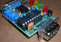
Here is a picture of a completed tracker I packaged for the club. It uses a 25Ah gel cell battery, an existing TinyTrack2 in a bud box (grey in the photo), the Delorme Earthmate (yellow) GPS, and the Yaesu tranceiver. I cut a piece of aluminum plate to fit under the handle area on the lid of the toolbox and mounted it to the toolbox. I then fixed the radio's mobile mount to the plate, and the radio to its mount. To keep the heavy battery from sliding around, I cut a scrap of 1/2" pine board to fit the inside profile of the toolbox and attached it in place with a few wood screws. What is not in this picture is the 1/4 wave mag mount antenna and coax. There are U shaped cuts in each end of the toolbox that will allow the antenna cable and the GPS cabling to exit the box and the lid can be secured as normal. |
UMX-5 and -6
TInyTrack 3+ (TT3+), Icom IC-25H, Deluo GPS WAAS
The club recently purchased the latest TinyTrack, the 3+ version, and Deluo GPS units. These are VERY compact, and will make great person carryable, portable trackers!
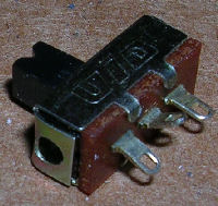
| I scratched my head as to how to add the switching functionality to these TT3+ units without loosing any convenience of packaging / size, etc. Digging through my junkbox I came up with a number of tiny SPDT slide switches. | 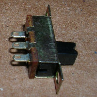 |
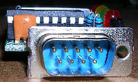
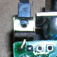
I examined the schematic for the revised TT3+ and identified the jumper where a switch might be placed to select between the 2 profiles, then located the pads for this on the PCB. Interestingly enough they moved from the previous version (TT3), and this is a good thing! They are near the edge of the board, next to the GPS/Computer 9 pin port.
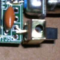
I decided that there was space enough here to locate the switch, with some judicious trimming of the DB9, and if the pins on the switch were bent just so, it could be soldered directly to the PCB. |
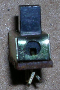  |
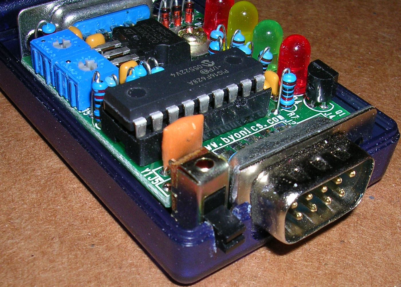
Marking the needed space, I broke out the Dremel & carefully trimmed the DB9. WIth some connectors of this type you need to be wary that the hole is peened and is the means that holds the metal shell together. If it looks like the shell may come apart, you can use a soldering iron to place a bit of solder in the seam to hold it together.
The spacing between the pins of the switch are such that they capture the PCB nicely.
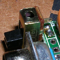
Using a small ruler I transferred the switch outline to the plastic case, and with an X-Acto razor saw, knife and a needle file I trimmed the opening as needed.

Performing the modification in this fashion allows the PCB to be removed without any additional wires to be delt with, and I think compliments the small form factor of the TinyTrack 3+.
Then I moved on to packaging the tracker components.
I liked how the previous units turned out, so I tried to continue with a similar design. The IC-25H uses a slide-in mount, so I cut another piece of aluminum plate to fit in the top of the toolbox, inside one of the top-accessable little compartments, and attached the radio mount to it. I stuck with the same battery retaining scheme as before. As this version of tracker will be using the TT3+ in its plastic case, I needed to locate it somewhere. I decided on the old Velcro trick, and here it is, stuck to the mobile radio bracket. |
After some reading of the TT3+ and Icom 25H manuals, I sketched out the cable harness.
| Here is a photo of the harness, minus the fusing for the TT3+, and its Anderson connectors. The TT3+ will share power connectors with the radio when completed. |